
|
All the instructions in MU0 processor instruction-set are of fixed-length of 16-bit. First 4 MSBs are the op-code bits which uniquely indicate each instruction while remaining 12 LSBs indicate address of the non-implicit operand. 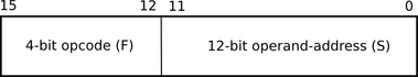 Since the op-code is 4-bit, 16 distinct instructions can be defined. However, MU0 defines & implements only 8 instructions. These instructions are: 1. op-code 0000 : LDA S i.e. load into accumulator the operand from memory location addressed as 'S'. 2. op-code 0001 : STO S i.e. store the content of accumulator register at the memory location addressed as ''S'. 3. op-code 0010 : ADD S ACC = ACC + [S] i.e. add content of memory location addressed as 'S with content of accumulator and save result at accumulator. 4. op-code 0011 : SUB S ACC = ACC – [S] 5. op-code 0100 : JMP S jump to the memory location addressed as 'S'. This will unconditionally change the program flow. PC = [S] 6. op-code 0101 : JGE S if ACC>=0, then jump. This is conditional jump with condition that alu result is positive. 7. op-code 0110 : JNE S another conditional jump with condition that ACC content is non-zero 8. op-code 0111 : STP stop the program execution Note that 'S' mentioned in all but last instructions, is 12-bit LSB from instruction. The op-codes 1000 to 1111 are all reserved for future expansion. (all op-codes in binary format). As the instruction set shows the programmers point-of -view towards the processor architecture, from the above discussed instructions we can say that there are only two user-visible (programmer-visible) registers in MU0 viz. ACC (accumulator) and PC (program counter). Instruction Execution: The instructions are executed in three phases viz. FETCH, DECODE and EXECUTE. FETCH: fetch the 16-bit instruction from memory into the instruction-register (IR) and then increment the PC content (PC = PC + 1). DECODE: The fetched instruction goes to the instruction decoder (control unit) and appropriate control signal are set by decoder. EXECUTE: - get the operands required for processing instruction. Operand comes from memory for LDA, ADD and SUB instructions; and from instruction itself for all 3 branching (jump) instructions. - carry-out the actual operation ALU operation for ADD, SUB - write-back the result to destination to ACC for ADD, SUB; to memory for STO instructions; to PC for branch instructions. - for STP instruction, nothing happens at execute step but processor remains in same state forever (until reset). Let's explore ALU design in next post. Connect with Digital Byte on facebook to get updates.
0 Comments
Leave a Reply. |
The Digital Byte App.
Like facebook page to get updates :
ArchivesCategories
All
|
 RSS Feed
